LVC Watlow limit control

Basic Limit Controller

LIMIT CONTROL, PID Watlow PM Integrated Control

Digital PID Limit Control

Multi-zone Controller Watlow EZ-Zone RM

Rail Mount Zone Limit

When Should You Use a Limit Controller?

PTSHEAT recommends a Process Limit Control in an application that is very important.  Limit controllers should be used for processes where there is a safety or quality requirement to protect a product or appliance from damage caused by excessive temperatures.

Typical Usage and Benefits

Limit devices are used in process control applications where independent limit switching for over or under temperature is required.  If the pre-set temperature limit is exceeded then the output switches to shut down the system.  This is a redundant system Loop to protect the primary Process Loop.

A limit control is often used in conjunction with a loop controller.  It will generally accept a variety of inputs such as thermocouple, RTD, or process inputs, then allowing for high or low temperature inputs to be set.  Limit controllers are used in a variety of applications, particularly industrial ovens and furnaces applications as well as by the life science industry.  A limit control should be a FM Approved device for a definite purpose OPEN or CLOSURE output.

One of our very popular limits is the Watlow EZ Zone PM. Panel mount temperature limit.  This controller is FM Approved. Used for programmable Process Protection. Set High limit, Low Limit, Deviation limit, or any combination. The EZ Zone Controller is a easy to work with unit that can be ordered / supplied in a Basic version (PM EZ Zone EXPRESS) with limited functions. This will be a control that has less menus for a more simple application. The EZ Zone Controller is also ordered / supplied in an integrated version (PM EZ Zone) with more advanced functions. This will be a control that has more menus and features where you can Set-up advanced parameters for process and temperature management. Watlow controls all come with a standard 3 year warranty. Watlow controls win every award for user friendliness and design.

Our engineers can walk you through the process of selection for the right protection control.  We have over 55 years of combined technical support working in the industrial control and process measurement.  We design and setup new applications for OEMs and end users.  We redesign and help make existing applications better.  What is the best control for my process?  How can I make this process better?  How can I make this process more efficient?  If you are asking these questions, then PTS is your source for improved process support!

Here are a few of the LIMIT Controller Options we propose:

Watlow PM PLUS SERIES PID & Integrated Limit Panel Mount Controller

Watlow’s PM PLUS™, the enhanced EZ-ZONE® PM, is now more intuitive and features an enhanced interface for easier programming and readability with a SMOOTH-TOUCH™ keypad creating an industry leading user experience. The PM PLUS is backwards compatible with legacy EZ-ZONE PM controllers but offers many user upgrades including an intuitive menu flow allowing the controller to be easily configured. It also continues to offer the industry leading Bluetooth® connectivity with the EZ-LINK™ mobile app for remote access capability and full descriptions of parameters and error codes. The PM PLUS improves the user experience by reducing the complexity at the front of the control while eliminating the dependency of cables when configuring the product. Like the original EZ-ZONE PM, the PM PLUS can be ordered as a PID controller, or an integrated controller with multiple functions combined into one. Replaces the EZ-Zone PM controller, Series 93, Series 965, Series 96, and ALL brands of panel mount PID controllers.

Performance Features


Description Information
TRU-TUNE®+ Adaptive Control Yes
Agency Approvals UL® listed, CSA, CE, RoHS, W.E.E.E., FM, SEMI F47-0200, Class 1, Div. 2 rating on selected models
Alarms Yes
Communication Protocols
Bluetooth
Modbus® RTU
EtherNet/IP™
Modbus® TCP
PROFIBUS DP
DeviceNet™
SAE J1939 CAN Bus
Standard Bus
Control/Limit Loops 1
Max Output 15A NO-ARC
Mounting 1/16 DIN Panel Mount
Profiling Yes

BUY NOW – Click Here to Visit our PTSHEAT Store!!!

Brochure:

Watlow PM PLUS User Manual:  PM PLUS PID Integrated 6-8-9 USER GUIDE -12-01-21

Watlow PM Brochure:  PM PLUS BROCHURE SELECTION GUIDE


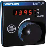
Watlow LV Limit Panel Mount Controller

Watlow’s microprocessor-based temperature limit controller provides an economical solution for applications requiring temperature limit control. Limits are available in a broad range of packaging options, allowing selection of the best version for an application. The temperature limit controller Series LV is available with an operator interface and can be ordered in 1⁄8 DIN-square panel mount or DIN-rail mount design configurations. The variable SERIES LV temperature limit controller includes an operator interface for viewing and selecting the set point. A red, four-character seven segment LED displays the set point. Set point selection is made with a continuous turn rotary encoder. Operating range temperature values are customer defined in the product configuration part number. The temperature limit controllers are factory mutual (FM) approved with special UL® approval for the open board potted versions. Watlow’s limit controllers include industry leading service and support and are protected by a three-year warranty.

Performance Features

Description Information
TRU-TUNE®+ Adaptive Control No
Agency Approvals UL®, ANSI, NEMA 4X, 1P65, CE, CSA, FM, RoHS, W.E.E.E. (including potted version)
Alarms 0
Ambient Operating Range 0 to 70°C (32 to 158°F)
Control/Limit Loops 0/1
Max Monitor Channels 1
Max Output 8A
Mounting DIN-rail, Front panel
Profiling No
Display Height 0.28 in. (7 mm)
Warranty (Years) 3

BUY NOW – Click Here to Visit our PTSHEAT Store!!!

Brochure:

Watlow LV User Manual: Watlow LV Series user manual


FDC L Series High Limit ControlsL91 & L41

L91 & L41 High Limit L Series

High Limit Controls

L91 and L41 FM Approved High Limit Temperature Controls

  • Universal Temperature Input
  • Configurable Display Logic – SAFE
  • Remote Reset Digital Input
  • Simple to Use & Configure
  • Up to 2 Outputs
  • PC Configurable
  • Serial Communications (option)
  • Meets NFPA 86.8.16.6 to display temperature and setpoint

Series 7L

Series 7L High Limit Controls

High Limit Controls

Series 7L FM Approved High Limit Control

  • DIN Rail or Surface Mount
  • Compact – Simple – Reliable Design
  • Easy to Use
  • Remote Reset Digital Event Input
  • Dual F / C Temperature Ranges
  • Output: 5A Form C Relay (SPDT)
  • Low Voltage Power Input available


L91 & L41 FM Approved Limit Controls – Special Features
  • Thermocouple & RTD Input Types
  • Display Configurations for Normal non-alarm Condition
  • Display Logic while in Alarm Condition
  • How to Change Setpoint Value – Lock Mode
  • Alarm Logic and Configuration:
    • Process, Deviation, Deviation Band, Sensor Break, Alarm Silence
  • Event Input:
    • Remote Reset of Latched Alarm
    • Lock Unit

    View Minimum, Maximum PV Values & Time in Alarm

  • Communications:
    • RS485 Modbus
    • Analog Retransmission


________________________________________________________________________________

Thermocouple & RTD Input Types

The L91 & L41 accept the following thermocouple & RTD inputs:

  • Thermocouple Types: J, K, T, E, B, R, S, N, L, C & Platinell II
  • RTD 100ohm Types: DIN and JIS standards
  • Refer to Manual for linear mA & VDC input – note linear mA/VDC inputs are NOT FM approved.

________________________________________________________________________________

Display Configurations for Normal non-Alarm Condition

The L91 single display may be configured as shown below for normal non-alarm conditions. The L41’s upper display will always show Process Variable (temperature) in its’ upper display with the lower display configurable as shown below for non-alarm conditions.

  • Process Variable (applies to L91 only)
  • High SP1 or Low SP1
  • Display word SAFE

LED Annuciators: The Output status annuciator LEDs, OP1 and OP2 show the status of the output relay(s), the display values being degrees C or F may be viewed at any time showing status of the output relay(s).

L91: At any time the operator may view PV, High SP1, Low SP1, SP2 by depressing the scroll key and observing the annuciator below the display; the appropriate SP values will only be displayed if the control is so configured.

L41: At any time the operator may view High SP1, Low SP1, SP2 by depressing the scroll key with the appropriate SP description shown in the lower display and SP value in the upper display; the appropriate SP values will only be displayed if the control is so configured.

________________________________________________________________________________

Display Logic while in Alarm Condition

The L91 single display, when the process goes into either High or Low Alarm condition [output #1] the display will show Process Value [PV] and Output #1 annuciator LED will be energized.

At any time the operator may view PV, High SP1, Low SP1, SP2 by depressing the scroll key and observing the annuciator below the display interpret the display value. The appropriate SP values will only be displayed if the control is so configured.

The L41 dual display, when the process goes into either High or Low Alarm condition [output #1] the lower display will show the High or Low Alarm Setpoint that caused the Alarm. The top display will show the Process Variable (temperature) at all times except when the operator .

Both the L91 and L41 the High or Low Alarm relay will stay latched until the PV is no longer in alarm condition and the operator depresses the Reset key.

Both the L91 & L41 display logic will revert to non-alarm display configuration when the PV is no longer in alarm condition – see previous section “Display Configurations for Normal non-Alarm Condition”

________________________________________________________________________________

How to Change Setpoint Value – Lock & Unlock Mode

The L91 single display may view High Setpoint 1, Low Setpoint 1 and SP2 values (dependent upon unit configuration) may be viewed at any time by depressing the scroll key and watch the annuciator below the display to interpret the display value.

The L41 dual default display shows the temperature value on the upper display with the lower display as configured will show SAFE or values representing SP1 or SP2. The High Setpoint 1, Low Setpoint 1 and SP2 values (dependent upon unit configuration) may be viewed at any time by depressing the scroll key – the lower display will show HSP1, LSP1 and SP2 (dependent upon unit configuration) with the Setpoint value shown in the upper display.

The Setpoint value(s) are not adjustable for either control when the LOCK annuciator is energized.

With the limit control in the unlocked condition and appropriate setpoint annuciator shown use the up & down arrow keys to change the appropriate setpoint value.

The control is in the UNLOCK mode for three minutes after power-up and can be entered at any time by depressing the RESET key for a minimum of 4 seconds.

Using the Event Input as a Remote Reset disables the keypad UNLOCK function. The Remote Reset must be held in place for 4 seconds to allow SP changes.

Remote Reset is a standard feature on the L41 and an option on the single display L91.

________________________________________________________________________________

Alarm Logic & Configuration

L91 & L41 Output #1 is available as a mechanical relay, 1A triac or ssr driver output.

L91 Output #2 offers mutually exclusive options: mechanical relay, 1A triac, ssr driver, transmitter power supply, analog retransmission of SP or PV, RS485 Modbus communication or event input for remote reset. Discussion below assumes Output #2 is uses as an alarm relay, 1A triac or ssr driver output.

L41 Output #2 offers the following outputs: mechanical relay, 1A triac, ssr driver and transmitter power supply.

Configuration of both Output #1 and Output #2 alarm outputs: hysteresis value per Output, action with control failure, and upper & lower Setpoint limits within the operating range of the selected input.

Output #1: Latching Output available as a mechanical Form C  relay, 1A triac or ssr driver that may be configured as follows:

  • High Alarm
  • Low Alarm
  • High & Low Alarm [one relay having two Setpoints]

When the Process Variable is in an alarm condition Output #1 will latch its’ output. The output can be cleared only when the Process Variable is no longer in alarm and the operator depresses the RESET key.

Output #2: L91 Form A [spst] and L41 Form C [spst] 2amp relay, 1A triac or ssr driver that may be configured as follows:

  • SP2: Process High Alarm non-latching
  • SP2: Process High Alarm latching
  • SP2: Process Low Alarm non-latching
  • SP2: Process Low Alarm latching
  • Limit Annuciator Alarm [Alarm Silence – has same SP as output #1]]

The non-latching configuration function as a normal process alarm – relay changes when in alarm condition and returns to original state when the PV in no longer in alarm.

The latching configuration function the same as output#1, relay is latched until the Process Variable is no longer in alarm condition and the operator depresses the RESET key.

The Limit Annuciator [Alarm Silence] configuration:

  • The Alarm Limit Annuciator Setpoint is the same as output #1 [High Alarm, Low Alarm or High-Low Alarm].
  • When the PV goes into an alarm condition output #2 is in alarm as it has the same SP as output #1.
  • Typically the Limit Annuciator alarm output is wired to an external annuciator, i.e. light, buzzer, etc.
  • If the RESET key is depressed while the process is still in alarm Output #2 relay only will be cleared acting as an Alarm Silence

Limit Control Applications:

Protection of process loops when a high/Low temperature or process variable will cause lost heater component, manufactured product, production down-time, or a safety situation.

    [contact-form-7 id="1929" title="Phoenix Contact Form"]

    Your Name (required)

    Your Email (required)

    Your Phone Number (required)

    Subject

    Your Message